Building Statistics: Part 1
Building Name Kaiser Permanente Full Service Medical Office Building
Location and Site Largo, Maryland
Building Occupant Name Kaiser Permanente
Occupancy or function types Medical Office Building – Type II-B
Size 106,700 SF Addition; 129,000 SF Renovation
Number of Stories Above Grade Addition – 3 stories; Renovation – 4 stories
Primary Project Team
Owner Kaiser Permanente
www.kaiserpermanente.org
General Contractor DPR Construction
www.dpr.com
Construction Manager Jacobs
www.jacobs.com
Architect, Interiors, Structural Ellerbe Becket, Inc. (An AECOM Company)
& MEP Engineers www.ellerbebecket.com
Civil Engineer A. Morton Thomas & Associates, Inc.
www.amtengineering.com
Dates of Construction Notice to Proceed – June 10, 2011
Final Completion – July 2014
Actual Cost Information Total GMP - $40,000,000
GMP based on CD Documents Addition - $32,500,000; Renovation - $7,000,000
Project Delivery Method CM at Risk
Architecture
Kaiser Permanente is adding to and renovating its Largo medical office building. Originally built in 1998, the fourteen year old, four-story building will soon be accompanied by a three-story, 106,000 square foot addition, basically doubling its size. The exterior façade of the building is intended to very closely match the existing building so one will not be able to tell they were built almost a decade and a half apart, although there will be some key differences. Once the addition is complete, the renovation will take place. The interior of the addition will then be replicated in the existing building along with some department relocations and renovations.
A large clerestory will be utilized on the new third floor, bringing much more natural light into the space which will be comprised mostly of corridor and waiting areas. There is a glass curtain wall on a large area of the west elevation extending around staircase one. Also, a large amount of architecture will be expressed through the landscaping design and specific plant selection.
The first floor of the new addition will include the Imaging and Urgent Care Departments accompanied by the new pharmacy. There will also be a small generator yard on the southeast corner of the building. Medical Pulmonary, Medical Cardiology, Orthopedics, and Podiatry departments located on the second floor with general surgery and head/neck surgery. The top floor will consist of the Pre-Surgery Center, Recovery/Perioperative Services (PACU), Outpatient Surgery, Sterile Processing and a new staff lounge.
Major National Codes
- International Building Code 2006
- International Mechanical Code 2006
- International Plumbing Code 2006
- Life Safety Code 101 (NFPA) 2009
- National Fire Alarm Code (NFPA 72) 2007
- AIA Guidelines for Design & Construction of Hospitals and Healthcare Facilities (2006)
Zoning
- The Prince George’s County Zoning Ordinance
- Maximum exist access travel distance: 150 feet from door and 200 feet from any point if sprinklered
- Maximum common path of egress travel: 100 feet sprinklered
- Maximum length of dead end corridor: 50 feet sprinklered
- Suites more than 2500 square feet, two exits and access doors required
Historical Requirements
- There are no historical requirements for this location.
 Building Enclosure
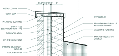
The exterior south and east facades primarily consist of two types of bonded brick (BR-1 to match existing building’s red brick and BR-2 to match existing tan colors). Behind the brick is an air barrier, ½” gypsum sheathing, vapor barrier, 6” metal studs with R-20 Batt Insulation.
Figure 1, above - Detail of brick facade and roofing material. Image courtesy of Ellerbe Becket, Inc.
Exterior Insulation and Finish System (EIFS) makes up a small portion of the facade. There are different variations of aluminum curtain wall that are all have one inch insulated glazing. There are three major types of glazing used; Green Tinted Insulating Vision Glass Unit with Low-E (GL-21), Ceramic-Coated Insulating Spandrel Glass (Gl-71) and Decorative Laminated Glass (GL-31A-F).
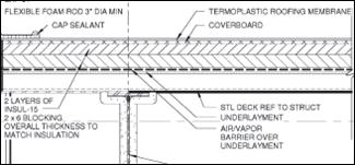 The roofing membrane is a white 60-mil, thermoplastic polyolefin (TPO) sheet. The membrane is overlapped and a bonding adhesive secures it to the sheet flashing below. There are two layers of four inch thick insulation on top of an air and vapor barrier. All of this is resting on gypsum coverboard which is mechanically fastened to the steel decking.
Figure 2 shows the thermoplastic polyolefin (TPO), coverboard, two layers of INSUL-15, air/vapor barrier all resting on steel decking. Image courtesy of Ellerbe Becket, Inc.
Sustainability Features
Although this building is not going to be LEED certified, there are many sustainable features in this medical office building. Throughout construction, material is being separated and recycled. A major passive feature of this building is the large cobrahead roof on the third floor of the addition which spans over 200 feet in length. This will bring in large amounts of natural daylight without overheating the space. The top layer of roofing consists of a thermoplastic membrane. This is a durable material that, because of its white color, will help the roof reflect light and absorb as little heat as possible, preventing the heat island effect.
 There will also be a drainage pond located between the Area C and the existing south wing. The pond will manage stormwater runoff and help improve the water quality of nearby sources. Another great thing incorporated into the landscape design is the natural vegetation that will be used surrounding the building. There is a lot less macadam and concrete around the perimeter of the building, allowing plenty of space for grass, shrubs and small trees native to the area. The area surrounding the building, once completed, will have entirely new pathways guided through a variety of vegetation.
Figure 3, above - clerrestory that stretches over 200 feet long for bringing in significant natural light. Personal photograph taken by Chris Pozza
Building Statistics: Part 2
The building systems primarily focused on in this section are the structural steel frame, electrical system, masonry and glass curtain wall systems. The structural steel frame has unique connections and could provide an interesting comparison in later analyses whether or not the system selected was cost effective. The electrical system is critical for a medical office building where people’s lives could depend on the building’s power. System redundancy is required with backup power in case of emergency. Finally, the exterior façade is mostly covered in brick veneer and a prefabricated aluminum curtain wall. The brick veneer could possibly be studied closer with an alternate precast system instead.
Demolition
Prior to start of construction, the existing surfaces, structures, paving and hardscape, making up what was once a parking lot, needed to be removed. A vestibule connected to the existing pharmacy needed to be demolished as well as a canopy at the loading dock. There are several locations where the addition connects to the existing building that will need to be opened in order to create corridors connecting the two structures. This will be done once the building is enclosed.
Once the renovation begins, there will be large amounts of demolition in the existing building as entire departments are being redone or moved. Zip walls will be required in areas during renovation work in order to limit the amount of dust and debris reaching neighboring areas. Being that this building was constructed in 1998, asbestos and lead are not a concern.
Excavation
There is no major excavation that required an additional form of support as this three-story addition’s first floor is a slab on grade with no basement. Minor excavation is required for the footings and foundations, and underground utilities. Utility trenches have been dug four inches deeper than the required bottom-of-pipe elevation to allow for a layer of aggregate bedding. Because the water level was well below foundations with only shallow excavations being done, no dewatering systems were necessary.
Structural Steel Frame
The main superstructure consists of wide flange beams, columns and girders. The first floor is a 5” thick concrete slab on grade. The rest of the building’s floor deck is 3” deep, 18 gage, composite metal deck with a 2.5” topping thickness. Typical floor beams range from W16x26 to W16x31 with girders ranging from W21x57 to W21x73.
Typical roof construction consists of 3” deep 20 gage steel roof deck. Decking has been specified based on a three span condition. Wide flange beams are used on the roof that primarily consists of W14x22, but W21x44 are required where supporting rooftop mechanical units. Roof girders mostly range from W21x44 to W21x62 with W18x40 and W18x50 spanning the perimeter. Hollow Structural Steel (HSS6x6x1/4) is used near the cobrahead roof. Steel is sloped toward roof drains.
This structure uses a unique moment connection, a Sideplate Frame System, which is shown in Figure 1.
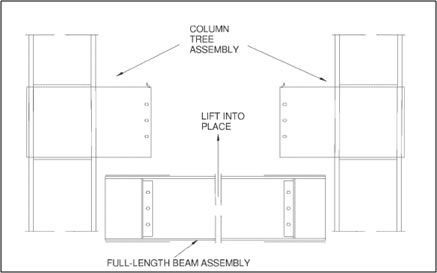
Figure 1 - Field erection method of a Sideplate Frame System. Image courtesy of Ellerbe Becket.
Sideplate connections were chosen over braced frames because they allow lateral framing to be located more conveniently and offer a greater cost economy. Smaller members are able to be used allowing for more space above ceilings and quicker steel erection. This system has previously been used on Kaiser Permanente facilities on the west coast.
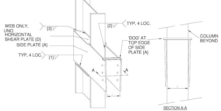
Figure 2 shows a 3D view of a side plate. Connections are prefabricated and require minor field work to bolt and weld members. The system itself is a beam-to-column moment connection. This can be a one- or two-sided connection that saves space and construction time. A shear plate is welded to the web of the column above and below the physical side plate with one on each side. The side plate itself extends beyond the column where the beam is then placed and bolted. Seen below in Figure 3 is an elevation and plan view of the Sideplate Frame System.
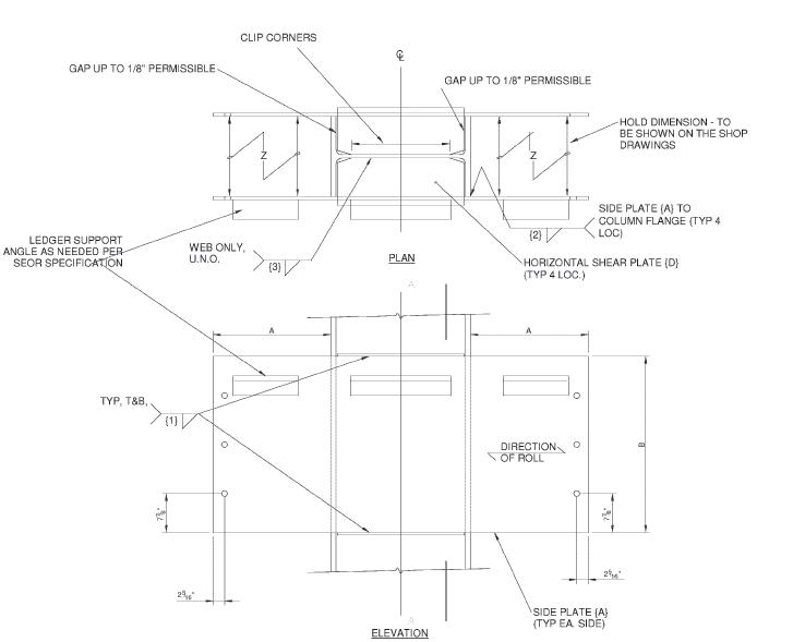
Figure 3 - Elevation and plan view of a Sideplate Frame System. Image courtesy of Ellerbe Becket.
Cast-in-Place Concrete
Cast-in-place concrete served several purposes for this structure. Shallow spread footings make up the foundation. The floor systems, including the 5” thick slab on grade, are all cast-in-place that are reinforced with welded wire fabric. Housekeeping pads are also required for all mechanical, electrical and plumbing equipment. The screen wall at the west loading dock was cast-in-place concrete as well. A concrete pump truck was utilized for the majority of concrete placement. Buggies were necessary for small placements such as housekeeping pads.
Precast Concrete
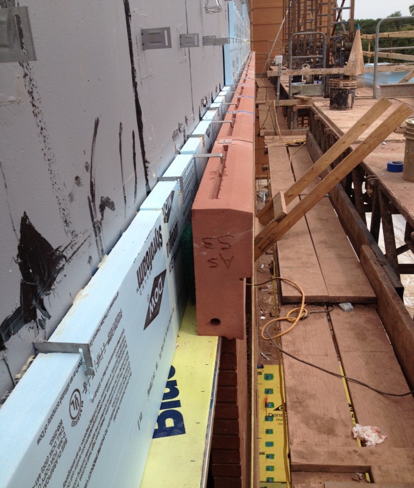
Although the neighboring parking deck is predominantly brick-clad architectural precast, the addition uses very little precast; however, precast concrete was used as an architectural feature to make a smooth transition from the existing to new structure. This accent band can be seen going in place in Figure 4, along with the vapor barrier, insulation and necessary steel tie-backs. The band itself is called out in red below in Figure 5. It can be seen that a color near that of the brick used blends nicely with the window sills and accent bands. An all-terrain forklift was used to lift precast to Fraco Lifts from which pieces were placed.
Figure 4 - Precast concrete can be seen above which make up the accent band along with east elevation. Personal photograph taken by Chris Pozza.
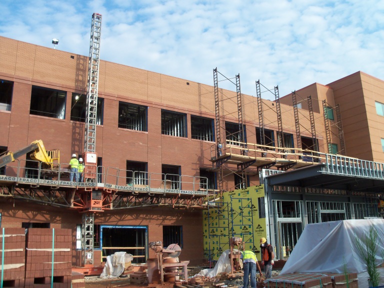
Figure 5 - Architectural precast concrete is seen under window sills and spanning the addition above the third story windows. Personal Photograph taken by Chris Pozza.
Mechanical System
Four rooftop air conditioning units resting on 30” high roof curbs will be responsible for the building’s air conditioning. Rooftop units one, two, and three (RTU-1, -2, -3) will serve spaces on each floor, with output capacity ranging from 26,000 to 34,000 cubic feet per minute (CFM). The fourth (RTU-4) is dedicated to the third floor operating rooms, with a capacity of 21,600 CFM. Each supply and return fan will be equipped with a variable frequency drive (VFD). Each unit includes a fan inlet airflow measuring station, two banks of filters, along with economizing dampers and controls to provide free cooling when outdoor conditions are suitable. A few other energy conservation measures will be taken for this system. Operating suites have setback controls for unoccupied periods and the mechanical system controls will provide and optimize energy efficiency. A direct digital Energy Management System (EMS) will optimize units operation.
Imaging and MRI suites will have smaller dedicated split air conditioning units. New terminal units with electric reheat coils will be included with variable air volume (VAV) and constant air volume (CAV) units, which will be the primary source of heating. The majority of the building’s air terminal units are CAV units. Both operate through a direct digital control (DDC) system with an adjustable temperature set point. When VAV boxes are supplying occupied spaces, a space thermostat controls the damper to maintain temperature. When heating is required, the damper will close to a minimal position, while the reheat coil valve opens in raise room temperature. The opposite takes place for cooling. For occupied spaces controlled by CAV units, air dampers are fixed at modes defined for each specific space on plans. The big difference between the VAV and CAV units is that CAV’s include humidity isolation valves to control and maintain humidity levels.
Chillers will be closed-loop systems that use non-CFC/HCFC R404a refrigerant. Each chiller has a cooling capacity of 118.8 thousand BTU per hour (MBH), 15 horsepower (HP) compressor, operating weight of 3,500 pounds, and run on 460 volts and are three-phase. Chillers are located on the rooftop of Area B, as seen below in Figure 6.
A unique feature is the cryogen vent which is required for the MRI equipment. This vent allows the superconducting liquid, used to keep magnets from overheating, to be dissipated from the building in the event of an unexpected shutdown, also known as a quench. The vent runs from the MRI suite through the building’s partition walls until exiting the building on the roof.
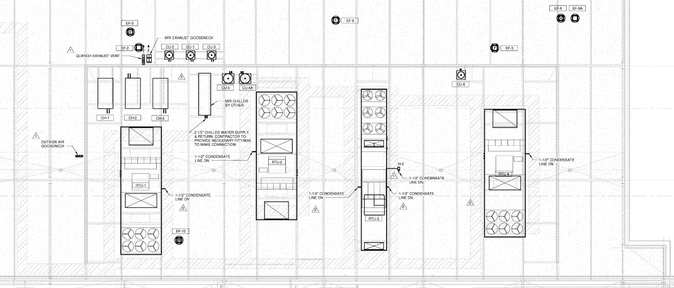
Figure 6 - Plan view of Area B's rooftop and the location of the building's major mechanical components. Rooftop units, chillers, exhaust fans, and even the cryogen vent exaust vent. Image courtesy of Ellerbe Becket.
A 6” fire and domestic water service lines will be split from the service provider to supply this building. A double check valve backflow preventer will be provided in the fire main supplying the 50 horsepower fire pump. The fire pump serves two standpipes in risers. Every floor will have a sprinkler branch, control valve, tamper switch and a flow switch that are connected to the fire alarm panel. Concealed sprinklers will be provided for public spaces and pendent type sprinklers will be located in ceilings of patient and administrative rooms. A dry-pipe sprinkler system will be provided for the main patient entrance canopies.
Main distribution piping for medical gas will be installed in the ceiling space of the first floor only. Medical gas wall outlets and piping will be color coded and labeled for easy identification during construction or future maintenance. From the first floor, piping will rise to serve outlets in second and third floors rooms, including operating suites, pre-operation areas, and procedure rooms. Piping will branch off of risers and directly connect to headwall units, equipment booms, and wall outlets. Medical gas includes oxygen, nitrous oxide, carbon dioxide, and nitrogen. The entire med gas system will be linked to the Building Automation System (BAS).
Electrical System
Pepco Power is the electric utility supplier to the existing building. The new service for the three-story addition is going to include a service yard on the southeast corner of the building. The electrical system’s service connects to a Pepco Power supply that consists of a 13.2 kV feeder serving a utility provided 480/277 Volt Pad mounted transformer, which will be fed from two sources in a three-way, concrete-encased ductbank. These two sources provide the necessary redundancy for the new building addition and do not affect the existing building’s systems. There will be a one-way and two-way concrete encased ductbank running to an existing Pepco Pole. From the service yard, a 15-way concrete-encased ductbank will run to the main switchboard.
Also in the service yard are two 1,250 KW Diesel generators which are connected to the addition’s paralleling gear. Between the paralleling gear and Switchboard MDS are eight main circuit breakers (MCB) and a fire pump; each of which have an automatic transfer switch to transfer the emergency distribution system loads from the Pepco Power source to the emergency generators. The main switch board and paralleling gear are both 4,000 Amp, 480/277V, and three-phase. Dry-type transformers are typically found throughout the building in electric rooms, ranging in size from 45 to 150 KVA, with the most common being 75 KVA. The main electric room is adjacent to the main mechanical room in the southwest corner of Area C. There are several smaller electric rooms on floors two and three.
The building uninterruptible power supply (UPS) for the addition will operate in union with the existing building’s electrical system. Its purpose is to provide back-up and distribution for critical electrical loads. The system is comprised of a single 60 KVA, 54 KW UPS module. Also included is multiple battery-powered system capable of a 15-minute run time at this load.
Lighting
A three-phase, 277V, 20 KVA UPS System with a 90 minute battery back-up will be specifically for emergency lighting applications. 277V, 3500/4100 Kelvin fluorescent fixtures dominate the new addition although there are some 120V incandescent fixtures used in areas for special use or decorative applications and include dimmers. The predominant luminaire in corridors, offices and patient rooms will be 2’ by 4’ recessed ceiling fixtures with either two or three 32 watt T8 lamps. Waiting areas and imaging rooms are generally comprised of round recessed LED fixtures. The MRI room will use 200 watt down lights actually running on DC power specifically rated for MRI suites. Exterior lighting is mainly comprised of 100 watt, HID lensed downlights that are recessed in the exterior canopies on the east and south ends of the addition.
Masonry
Non-load bearing brick veneer over steel studs will be the primary building façade. There are two colors of brick used that match the existing building’s colors. Mortar color presented a challenge as it was difficult to produce the same color found on the existing building, but after several attempts, the desired color was eventually matched.
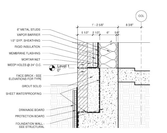
Figure 7 - Detail of exterior masonry wall at foundation. Image courtesy of Ellerbe Becket.
Fraco Lifts were set up around the perimeter of areas placing brick. MasonKing lifts were required in areas where veneer work was done above rooftops, which are shown and described below in Figures 8 and 9.
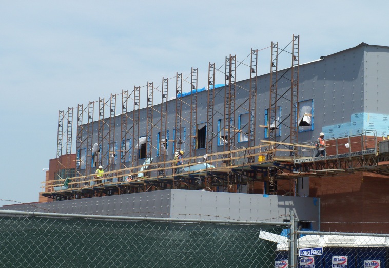
Figure 8 - View looking at southwest elevation. A MasonKing lift is required in areas where work is done above rooftops. These lifts have to be simultaneously cranked by hand to be lowered or raised. Personal photograph taken by Chris Pozza.
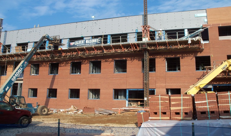
Figure 9 - View looking at east elevation. Fraco Lifts are used around exterior to provide efficient flow of construction along a large percentage of elevation at a time. Materials are lifted into place with a boom lift. Personal photograph taken by Chris Pozza.
Curtain Wall
Prefabricated aluminum curtain wall systems are used mostly on the west and south elevations. This wall system consists of 2.5” wide by 8” deep exposed mullions and caps at multistory locations. At low rise locations, 2.5” wide by 6” deep exposed mullions and caps are used. There are horizontal and vertical expressed caps along with the two main types of glass; 1” clear low E coated insulated glass and 1” spandrel glass. The system is thermally broken and designed to accommodate horizontal and vertical movement. Glass is lifted into place and sealed by two workers using a using JLG lift.
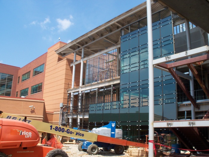
Figure 10 - View of west elevation curtain wall system under construction. The boom lift used during construction of the façade system can be seen at the bottom of the photo. Personal photograph taken by Chris Pozza.
An exterior view of glass curtain wall going in place is shown above in Figure 10. Figure 11 is an interior view looking at the same area on the second floor is seen. Eventually, this area will be a corridor into the existing building (straight ahead) with waiting areas to the right, getting plenty of natural daylight.
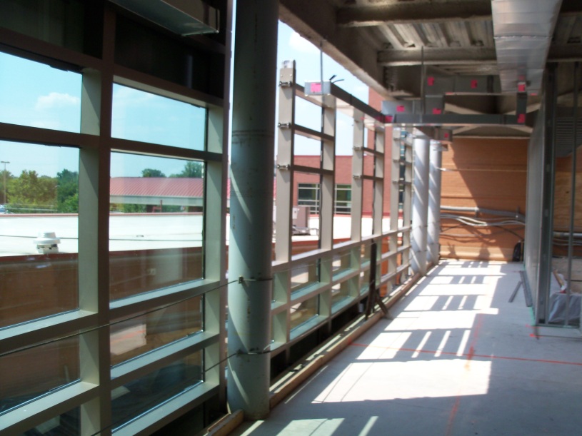
Figure 11 – Interior view of west elevation curtain wall system under construction. Personal photograph taken by Chris Pozza.
Exterior Insulation and Finish System (EIFS)
An EIF System over steel stud back-ups is used primarily on the underside of overhangs and screenwalls around rooftop units. Primarily, it’s used in areas where it actually cannot be seen. At non-insulated soffit locations, EIFS is applied directly over the water resistant sheathing. The EIFS will have an acrylic finish coat with a standard light-sand, troweled finish. The color has been chosen to match the EIFS in the existing building.
Metal Panel
There are three types of metal panels used on this project. Insulated Aluminum Panels (MP-1) are 2” thick insulated metal panels that are bonded to factory formed-in-place core with a tongue-and-groove joint. Composite Aluminum Panels (MP-2) are comprised of two sheets of aluminum sandwiching a core of extruded thermoplastic. This system is formed in a continuous process with no adhesives between unlike materials. Preformed Exposed Fastened Metal Panels (MP-3) are fabricated from zinc-coated steel. These will largely be used at the elevated roof of the clerestory window shown below in Figure 13.
Sustainability Features
lthough this building is not going to be LEED certified, there are many sustainable features in this medical office building. Construction is guided by the Green Guide for Health Care, although contracts are not tied to it. Throughout construction, material is being separated and recycled. A major passive feature of this building is the large cobrahead roof on the third floor of the addition which spans over 200 feet in length, shown in Figure 12. A cobrahead roof refers to the shape of the roof. This will bring in large amounts of natural daylight without overheating the space. The top layer of roofing consists of a thermoplastic membrane. This is a durable material that, because of its white color, will help the roof reflect light and absorb as little heat as possible, preventing the heat island effect.
There will also be a drainage pond located between the Area C and the existing south wing. The pond will manage storm water runoff and help improve the water quality of nearby sources. Another sustainable feature incorporated into the landscape design is the natural vegetation that will be used surrounding the building. There is a lot less macadam and concrete around the perimeter of the building, allowing plenty of space for grass, shrubs and small trees native to the area. The area surrounding the building, once completed, will have entirely new pathways guided through a variety of vegetation. The plantings have specifically been chosen for their indigenous characteristics and do not require more water than the natural environment provides; therefore, an irrigation system is not required.
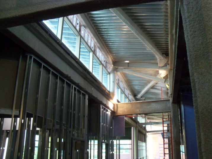
Figure 12 - Shown above is the clerestory that stretches over 200 feet long and bringing in natural light. Personal photograph taken by Chris Pozza